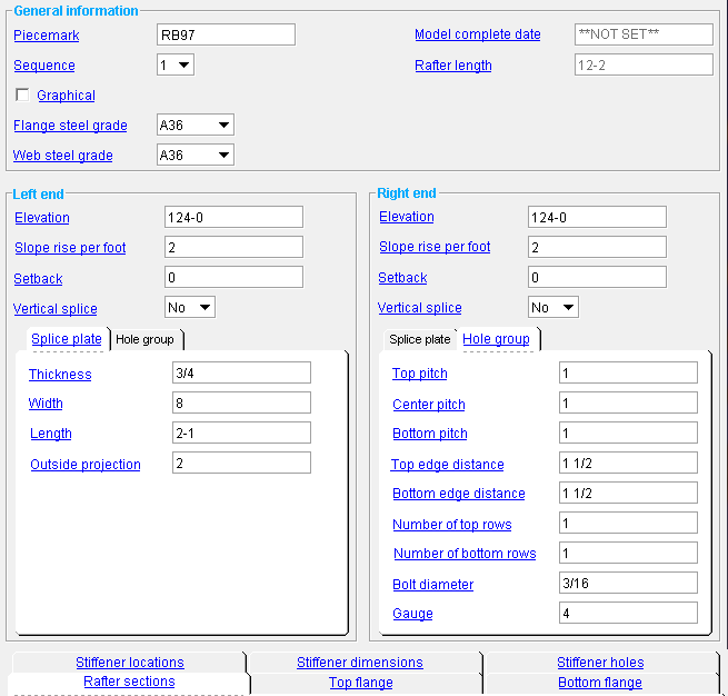
Engineered Rafter ( Modeling > F2 >  Other > " Engineered Rafter ")
Tool summary :


The " OK " button is disabled (grayed out) to indicate a validation error. Hover the " OK " button with your mouse pointer to get a listing of settings you need to change on this window. When all settings are valid, the " OK " button is enabled. 

Red-colored highlighting identifies an entry that is invalid. You need to change that setting, or you will not be able to close this window using " OK ."
Also see :
- Custom members (topic)
page 1 | contents | F2 > other > engineered rafter | locate workpoints | top
Locating work points :
To add an engineered rafter (in Modeling ):
Method 1 : Press F2 or choose Model > Member > Prompt for Member Type , then double-click " Engineered Rafter " on the Member Type Selection window.
Methods 2, 3 & 4 : An Engineered Rafter icon can be added to your toolbar (classic) or ribbon (lightning). The icon, keyboard shortcut or context menu command can be found in the group named ' Model -- Member '. For lightning, Customize Interface is used to configure ribbons, keyboards, the context menu and modes.
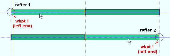
Two work points are required to lay out an engineered rafter. The first point that you locate is the left end of the member. The settings that are under " Left end " on this window pertain to the first-located-point end.
|
|
In this example, User and Site Options > Modeling > " Show member origin " and " Highlight surfaces " are turned on ( |
To lay out a sloping rafter, you may find it easiest to locate work points in a plan view then adjust the " Elevation " of the left- or right-end work point on this window.
page 1 | contents | F2 > other > engineered rafter | locate workpoints | top
------ General information ------
Piecemark: The member piecemark of the engineered rafter.
Typing in characters makes the piecemark a user piecemark .
To clear a user piecemark, or if you are adding a new engineered rafter, leave this field blank. SDS2 piecemarking will assign a system piecemark when you press " OK ."
Sequence: Any sequence name from the Sequence Names setup list can be entered. Either type the sequence, or you can press the "file cabinet" browse button ( ![]() ) and double-click any sequence name that is on the list.
) and double-click any sequence name that is on the list.
Tip: To add a new sequence to the Sequence Names setup list so that it can be selected here, first increase the number of " Maximum sequences " that are available.
Graphical : You should check this box when you no longer want the engineered rafter to undergo Process and Create Solids . For example, when you are ready to begin manually modifying the member using Edit Material , material cutting operations, or etc. Click here for more information.
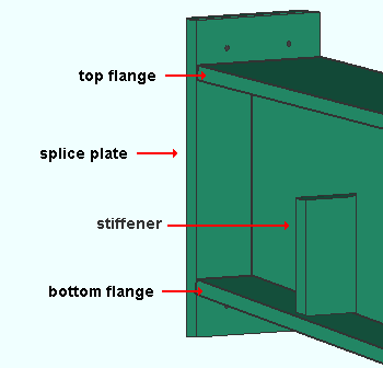
Flange steel grade: The " Steel grade " of various rectangular plates that make up this member. These rectangular plates include the splice plates, the member's top and bottom flange plates, and the stiffener plates.
|
If you select ' Materia l' as the selection filter and double-click an engineered rafter's top flange, splice plate, stiffener or bottom flange, the Rectangular Plate Material window will open. The " Steel grade " on that window will match the " Flange steel grade " that is entered here. |
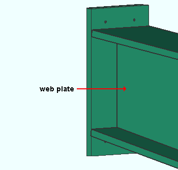
Web steel grade: The " Steel grade " of the engineered rafter's web plate(s). A single engineered rafter member can have multiple web plates when multiple " Rafter sections " are specified.
|
If you select ' Materia l' as the selection filter and double-click an engineered rafter's web, the Multi-sided Flat Plate Material window will open. The " Steel grade " on that window will match the " Web steel grade " that is entered here. |
Model complete date: read-only .. The " Model completed " status of this member can be set using Update Attributes . You cannot set the " Model complete date " here, on this window.
' **NOT SET** ' indicates that this window is fully editable.
' month day year ' indicates that all fields on this window are in a disabled , read-only state due to the " Model completed " date having been set on this member, using Update Attributes , not necessarily on the reported date.
Also see: " Model complete date "
Rafter length: Read-only . The actual length of this rafter's workline (in the primary dimension " Units "). This distance is calculated from the X and Y and Z global coordinates of the work points located when the rafter was added . Left- and right-end " Setbacks " are subtracted from the total.
Since a change in the left- and/or right-end " Elevation " changes the location of the engineered rafter's work points, making such a change also results in a recalculation of the " Rafter length " when you press " OK ."
page 1 | contents | F2 > other > engineered rafter | locate workpoints | top
------ Left end ------ || ------ Right end ------
Elevation: The left-end elevation and right-end elevation in the primary dimension " Units " or other units .
The left-end elevation is the Z axis coordinate of the 1st work point that was located. Changing the " Elevation " moves the work point's Z coordinate to that elevation. The top, left end of the web plate will be located at this point.
The right-end elevation of the 2nd work point that was located. Changing the " Elevation " moves the work point's Z coordinate to that elevation.
Unlike a beam, column, brace or joist, the left-end work point of an engineered rafter is the 1st point that was located when the engineered rafter was added. The right-end work point is the 2nd point that was located.
To determine the end elevation on an engineered rafter in the 3D model, use Construction Line Add or a similar tool, select EXPT as the Locate option, then move the point location target to the work point at the desired end of the rafter and reference the Z coordinate reported in the X-Y-Z display .
Slope rise per foot: A positive or negative distance that describes the slope of the top flange. Changing this value can affect the results that you make to " Vertical splice " but does not affect the actual slope of the top flange.
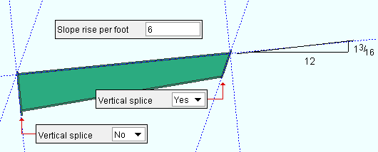
Tip 1: Generally it is best to let Engineered Rafter calculate this value for you. If, for example, you add a rafter by locating two points in a plan view then change the " Elevation " then press " OK ," Engineered Rafter will automatically recalculate the " Slope rise per foot " and you will find that recalculated value when you open this window.
Tip 2: If the rafter is modeled as horizontal but will be used for a sloping roof, you may want to enter the slope of that roof here.
Setback: The positive or negative (-) distance (in the appropriate " Units ") that you want the left- or right-end of the engineered rafter to be offset from its work point.
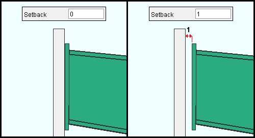
A ' positive setback ' makes the engineered rafter shorter. Entering a positive distance then pressing " OK " results in a smaller " Rafter length " being reported when you re-open this window.
A ' negative (-) material setback ' makes the engineered rafter longer.
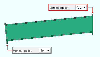
' Yes ' results in the plate at this end of the rafter being oriented vertically. Engineered Rafter calculates vertical based on the " Slope rise per foot " along with the actual slope of the rafter's workline.
' No ' results in the plate at the end of the rafter being oriented perpendicular to the top flange of the rafter.
| Splice plate | Hole group |
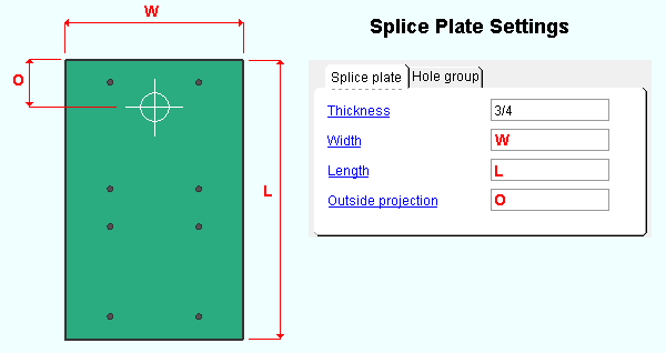
Thickness: A distance (in the primary dimension " Units " or other units ). This is the" Material thickness " of the rectangular plate that is the splice plate on this end of the member. The steel grade for this plate is the " Flange steel grade ."
Width: A distance (in the primary dimension " Units " or other units ). This is the " Material width " of the rectangular plate that is the splice plate on this end of the member.
Length: A distance (in the primary dimension " Units " or other units ). This is the " Order length " of the rectangular plate that is the splice plate on this end of the member.
Outside projection: The distance (in the primary dimension " Units " or other units ) that the splice plate projects above the work point elevation of the engineered rafter.
Increasing this distance slides the splice plate up. Consequently, you may want to also adjust the " Length " of the splice plate so that it projects the distance that you want below the bottom flange.
| Splice plate | Hole group |
Under Construction.
page 1 | contents | F2 > other > engineered rafter | locate workpoints | top
| Stiffener locations | Stiffener dimensions | Stiffener holes |
| Rafter sections | Top flange | Bottom flange |
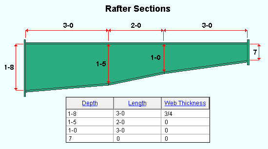
Depth: A distance (in the primary dimension " Units " or other units ). This distance is the depth of the web of the engineered rafter at a particular point along its workline.
" Depth " is measured perpendicular to the workline of the engineered rafter member.
In the first row of the " Rafter sections " tab, the particular point that the " Depth " of the rafter's web is measured at is the point on the web that is closest to point 1 (the left end) of the rafter member.
In the second row, the point at which the " Depth " is measured is a particular distance from the point at which the " Depth " in the first row was measured. That particular distance is approximately (and may be exactly) the " Length " specified in the 1st row.
" Depth " needs to be specified on a minimum of 2 lines, even if the depth at both ends is the same. The following example produces a single rectangular web plate made of Multi-sided Flat Plate Material (a flat plate layout).

Specifying one " Depth " on line one and a different " Depth " on line two results in a tapered web plate as shown in the example below.

Three " Depth " lines can be used to specify a web with two different tapers. A " Length " needs to also be specified for one of the sections. The length of the other section will be calculated automatically.

Depending on the amount of taper between sections on a web plate, the web plate may consist of a single Multi-sided Flat Plate Material or of more than one such plates. It
Length: A distance (in the primary dimension " Units " or other units ).
Rafter web sections are made up of Multi-sided Flat Plate Material (a flat plate layout).
The rafter web may be a single plate, or it may consist of multiple plates with gaps between them. Gaps may placed between plates if space is needed to prevent flanges from clashing.
The " Length " on each line in the " Rafter sections " tab correlates to the " Rafter length " minus the left- and right-end splice plate " Thickness " and any gaps placed between web section plates.
Web Thickness: A distance (in the primary dimension " Units " or other units ).
This is the " Material thickness " of the Multi-sided Flat Plate Material that is the engineered rafter's web plate.
page 1 | contents | F2 > other > engineered rafter | locate workpoints | top
| Stiffener locations | Stiffener dimensions | Stiffener holes |
| Rafter sections | Top flange | Bottom flange |
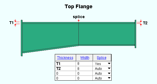
Thickness: A distance (in the primary dimension " Units " or other units ).
This is The " Material thickness " of the rectangular plate(s) that make up the top flange of this engineered rafter member.
You should enter a " Thickness " for as many sections as the top flange can potentially be divided into. The number of sections that the top flange can be divided into is the same as the number of sections that make up the web plate. In the above example, the top flange can be divided into two sections.
Width: A distance (in the primary dimension " Units " or other units ).
This is the " Material width " of the rectangular plate(s) that make up the top flange of this engineered rafter member.
You should enter a " Width " for as many sections as the top flange can potentially be divided into.
Splice: Yes or Auto . A splice is a gap between plates that make up the top flange. When no such gap is generated, the top flange consists of a single rectangular plate. One splice results in the top flange being composed of two separate flange plates. Two splices results in the top flange being composed of three separate flange plates.
' Auto ' produces a splice when one is required. In the above example, a splice is not required since the top flange could be fabricated using a single plate.
' Yes ' may be used to produce a splice when one is not required. In the above example, a splice is not required, but since ' Yes ' is selected, a splice is created. If ' Auto ' had been selected for the above example, the top flange would have consisted of a single rectangular plate. Since ' Yes ' is selected, the top flange consists of two plates.
page 1 | contents | F2 > other > engineered rafter | locate workpoints | top
| Stiffener locations | Stiffener dimensions | Stiffener holes |
| Rafter sections | Top flange | Bottom flange |
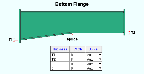
Thickness: A distance (in the primary dimension " Units " or other units ).
This is The " Material thickness " of the rectangular plate(s) that make up the bottom flange of this engineered rafter member.
You should enter a " Thickness " for as many sections as the bottom flange can potentially be divided into. The number of sections that the bottom flange can be divided into is the same as the number of sections that make up the web plate. In the above example, the bottom flange can be (and is) divided into two sections.
Width: A distance (in the primary dimension " Units " or other units ).
This is the " Material width " of the rectangular plate(s) that make up the bottom flange of this engineered rafter member.
You should enter a " Width " for as many sections as the bottom flange can potentially be divided into.
Splice: Yes or Auto . A splice is a gap between plates that make up the bottom flange. When no such gap is generated, the bottom flange consists of a single rectangular plate. One splice results in the bottom flange being composed of two separate flange plates. Two splices results in the bottom flange being composed of three separate flange plates.
' Auto ' produces a splice when one is required. In the above example, a splice is required since -- due to the tapering of the web, the bottom flange must be fabricated as two separate plates.
' Yes ' may be used to produce a splice when one is not required. In the above example, ' Yes ' would produce the same results as ' Auto ' because the bottom flange needs to be composed of two separate rectangular plates in order to be fabricated along the full length of the web.
page 1 | contents | F2 > other > engineered rafter | locate workpoints | top
| Rafter sections | Top flange | Bottom flange |
| Stiffener locations | Stiffener dimensions | Stiffener holes |
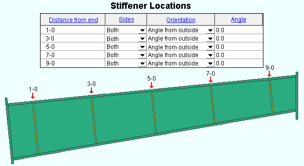
Distance from end: The distance (in the primary dimension " Units " or other units ) that the stiffener (or double stiffeners) are to be placed from the left end of the members material. The left end of an engineered rafter is the end associated with the first work point that was located when the member was added. The actual location of the left end of a member's material depends on the left-end " Setback " as well as the work point location.
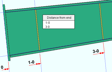
The stiffeners are placed in line with the interior of the bottom flange if their " Type " is ' Full from inside ' or ' Partial from inside '. The stiffeners are placed in line with the interior of the top flange if their " Type " is ' Full from outside ' or ' Partial from outside '.
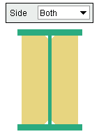
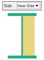
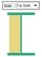
Sides: Both or Near Side or Far Side .
|
|
|
|
The bottom end of the rafter is shown in all three of these examples. The left end is the 1st point that was located when the rafter was added.
|
||
' Both ' places the stiffeners on both the near side and far side of the web of the rafter.
' Near Side ' places the stiffeners on the near side of the web. If you are looking at the web of a rafter, and the left end of the rafter is to your left, then you are looking at the near side web of the rafter.
' Far Side ' places the stiffeners on the far side of the rafter's web.
Orientation: Vertical or Angle from inside or Angle from outside .
' Vertical ' orients the stiffener vertical to the world. Any " Angle " that you enter for a stiffener that is set to ' Vertical ' will be ignored.
' Angle from inside ' orients the stiffener perpendicular to the bottom flange when the " Angle " is set to ' 0 ' (zero).
' Angle from outside ' orients the stiffener perpendicular to the top flange when the " Angle " is set to ' 0 ' (zero).
Angle: A positive or negative (-) number of degrees . This applies only to stiffeners whose " Orientation " is set to ' Angle from inside ' or ' Angle from outside '.
' 0 ' (zero) orients the stiffener perpendicular to the bottom flange when the " Orientation " is set to ' Angle from inside '. It orients the stiffener perpendicular to the top flange when the " Orientation " is set to ' Angle from outside '.
' A positive or negative non-zero value ' rotates the stiffener from its zero position that number of degrees.
Note: Any " Angle " you enter here is ignored when the stiffener's " Orientation " is set to ' Vertical '.
page 1 | contents | F2 > other > engineered rafter | locate workpoints | top
| Rafter sections | Top flange | Bottom flange |
| Stiffener locations | Stiffener dimensions | Stiffener holes |
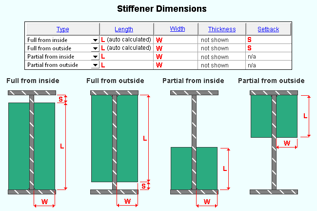
Type: Full from inside or Full from outside or Partial from inside or Partial from outside .
' Full from inside ' generates a full-depth stiffener that is flush from the bottom flange. You may enter a " Setback " from the top flange.
' Full from outside ' generates a full-depth stiffener that is flush from the top flange. You may enter a " Setback " from the bottom flange.
' Partial from inside ' generates a stiffener that is the " Length " that you enter. The stiffener will be flush with the bottom flange.
' Partial from outside ' generates a stiffener that is the " Length " that you enter. The stiffener will be flush with the top flange.
Length: The distance (in the primary dimension " Units " or other units ) that is the " Order length " of the rectangular plate that is the stiffener.
For a ' Full from inside ' or ' Full from outside ' stiffener, the " Length " is calculated automatically when you press " OK ." If you enter a " Length ," your entry will be overridden when you press " OK ."
For a ' Partial from inside ' or a ' Partial from outside ' stiffener, a stiffener that is the " Length " that you enter will be generated when you press " OK ."
Width: The distance (in the primary dimension " Units " or other units ) that is the " Material width " of the rectangular plate that is the stiffener.
Thickness: The distance (in the primary dimension " Units " or other units ) that is The " Material thickness " of the rectangular plate that is the stiffener.
Setback: The distance (in the primary dimension " Units " or other units ) that a full-depth stiffener will be set back from the top or bottom flange.
For a ' Full from inside ' stiffener, this distance is the gap between the top of the stiffener and the top flange.
For a ' Full from outside ' stiffener, this distance is the gap between the bottom of the stiffener and the bottom flange.
For a ' Partial from inside ' or a ' Partial from outside ' stiffener, a setback is not applicable . Any entry you make to " Setback " will be reset to ' 0 ' (zero) when you press " OK ."
page 1 | contents | F2 > other > engineered rafter | locate workpoints | top
| Rafter sections | Top flange | Bottom flange |
| Stiffener locations | Stiffener dimensions | Stiffener holes |
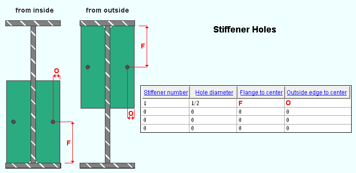
Stiffener number: 1 or 2 or 3 , etc. The stiffener whose position is specified in the 1st row under " Distance from end " is stiffener number 1. Stiffener number 2 is the stiffener specified in the 2nd row.
This number identifies the stiffener to which a hole is to be applied.
The number refers to a set of double stiffeners when ' Both ' is the stiffener's " Sides ." A hole defined on a line for double stiffener will be applied to both the near- and far-side stiffener.
To define two holes for the same stiffener (or the same pair of stiffeners), you need to enter the same stiffener number to two separate lines.
No stiffener is ever assigned the number 0. Changing the " Stiffener number " to ' 0 ' stops the hole definition on that line from being applied to any stiffener.
Hole diameter: The diameter of the hole in the stiffener(s) whose " Stiffener number " is specified for this line. You can enter a hole diameter in the primary dimension " Units " or other units .
![]() dia = hole diameter
dia = hole diameter
Flange to center: The distance (in the primary dimension " Units " or other units ) that the hole is centered from the interior of the top flange or bottom flange.
This dimension is measured from the interior of the bottom flange when ' Partial from inside ' or ' Full from inside ' is the stiffener " Type ."
This dimension is measured from the interior of the top flange when ' Partial from outside ' or ' Full from outside ' is the stiffener " Type ."
Outside edge to center: The distance (in the primary dimension " Units " or other units ) that the hole is centered from the outside edge of the stiffener. The outside edge is the stiffener edge that farthest from the web of the engineered rafter.
page 1 | contents | F2 > other > engineered rafter | locate workpoints | top
"Properties" opens the Edit Properties window, on which you can make entries to custom properties . If, at the time it was created, your current Job was set to use a legacy flavor, the window that opens is named Custom Properties , not Edit Properties .
The Edit Properties window can also be used to read "
Log " entries or review or type "
Notes ."
The " Properties " button is disabled ( grayed out ) when a new custom member is being added.
Tip: Model > Member > Properties is an alternative to this button. It opens the Edit Properties window directly, without your first having to open a member edit window.
" Status " opens the Member Status Review window, which can give you additional information about this engineered rafter, and which you can use to enter status information.
"OK" (or the Enter key) generates the engineered rafter member per the settings entered on this window.
Be aware of the following:
If the " OK " button is disabled (grayed out), click here for more information.
The " Rafter length " is recalculated when you press " OK ." If, for example, you changed the " Elevation " of either end or changed either end's " Setback ," a different, newly recalculated " Rafter length " will be reported the next time you open this window.
Stiffeners whose " Type " is ' Full from inside ' or ' Full from outside ' will have their " Length " recalculated. Any " Length " that the user has entered for a full-depth stiffener will be overridden.
Stiffeners whose " Type " is ' Partial from inside ' or ' Partial from outside ' will have their " Setback " set to ' 0 ' (zero).
The " Piecemark " that is shown, if it is a system piecemark, may change after you press " OK ." If there is no " Piecemark " shown, a system member piecemark will be assigned after you press " OK ."
"Cancel" (or the Esc key) closes this window and ends the Add Engineered Rafter or Edit Engineered Rafter operation. If you were adding a new engineered rafter, no engineered rafter will be added. If you were editing an engineered rafter, the engineered rafter will remain unchanged.
"Reset" undoes any changes made since you first opened this window.
page 1 | contents | F2 > other > engineered rafter | locate workpoints | top
